The place to be “complicated” is the Data List (Parameter Change) listings, lol.
It could have to do with the either/or nature of the AN-X engine’s FM and RING MOD. features
The Oscillators can be fed one to another to provide a MODULATOR:CARRIER (FM) relationship or they can be in a RING MODULATION configuration where the resulting tone is the sum + difference between the Oscillator’s Frequencies.
[PERFORMANCE] → Part Common selection → [EDIT/] → Filter / Amp → Mixing
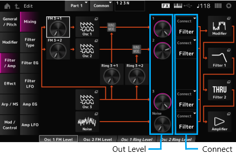
If you navigate to the “Filter/Amp” > “Mixing” screen of an AN-X Part, you can see how OSC 3 can be routed to OSC 1 and/or OSC 2… You can also see how the signal from OSC 3 can also be routed post the output of OSC 1 and/or OSC 2 for Ring Modulation. Rather than entering and modulating (as with FM routing), the OSC 3 output is set to do the Ring Mod thing where you hear both the addition (sum) of the frequencies and the subtraction (difference) of the frequencies (metallic, clangorous tones)
Notice, in the “OSC 1” SubDisplay, as you try to change values, RING MOD <—> FM, you can route OSC 3 —> OSC 1 via FM or via RING MOD… that’s what I mean by “either/or” scenario.
You have separate pathways for OSC 3 output:
from OSC 3 to OSC 1
from OSC 3 to OSC 2
![Image]()
Operate the RING MOD <—> FM Knob in the SubDisplay and watch the OSC FM LEVEL and the RING MOD LEVEL… in the MainDisplay
It could have to do with the either/or nature of the AN-X engine’s FM and RING MOD. features
The Oscillators can be fed one to another to provide a MODULATOR:CARRIER (FM) relationship or they can be in a RING MODULATION configuration where the resulting tone is the sum + difference between the Oscillator’s Frequencies.
[PERFORMANCE] → Part Common selection → [EDIT/] → Filter / Amp → Mixing
If you navigate to the “Filter/Amp” > “Mixing” screen of an AN-X Part, you can see how OSC 3 can be routed to OSC 1 and/or OSC 2… You can also see how the signal from OSC 3 can also be routed post the output of OSC 1 and/or OSC 2 for Ring Modulation. Rather than entering and modulating (as with FM routing), the OSC 3 output is set to do the Ring Mod thing where you hear both the addition (sum) of the frequencies and the subtraction (difference) of the frequencies (metallic, clangorous tones)
Notice, in the “OSC 1” SubDisplay, as you try to change values, RING MOD <—> FM, you can route OSC 3 —> OSC 1 via FM or via RING MOD… that’s what I mean by “either/or” scenario.
You have separate pathways for OSC 3 output:
from OSC 3 to OSC 1
from OSC 3 to OSC 2

Operate the RING MOD <—> FM Knob in the SubDisplay and watch the OSC FM LEVEL and the RING MOD LEVEL… in the MainDisplay
Statistics: Posted by Phil Clendeninn — Thu Dec 14, 2023 12:03 pm